M 51, also known as the Tourbillon galaxy (Whirlpool Galaxy in English) is a couple of galaxies located around 27.4 million light years in the constellation of Hunting dogs.
This famous couple is composed of a regular spiral galaxy massive whose diameter is estimated at 100 000 light years and a small irregular galaxy .
Spring star, it is one of the most famous galaxies of astrophotographers, with very pronounced colors and presenting beautiful nebulae, accentuated here by the joint use of a Halpha Hydrogen filter.
Noise reduction
The object of this article is to present my current method of noise reduction, the idea being above all to present a noise reduction approach, rather than a method which would be THE method to follow. Thereby this approach can be applied to software other than Pixinsight or Photoshop, as long as we understand the broad outlines.
We will deal with noise reduction on monochrome images (Luminance, or separate RGB layers or SHO), so people using a digital camera or color camera will have to extract the image beforehand. luminance of their images. (The reduction of chromatic noise may be the subject of a future article).
General
Linear noise reduction (Pixinsight)
Simple method
Advanced method
Noise reduction in nonlinear
With Pixnsight
With Photoshop
Noise reduction is one of the essential aspects of processing an astronomical image given the very low light of the subjects photographed.
We often talk about signal-to-noise ratio (SNR), an indicator of the quality of the transmission of a information which corresponds to the ratio between the captured signal by the sensor and the background noise also captured by the latter, whether of internal or external origin to this sensor.
The quality of the image will therefore be partly linked to the maximum increase in this ratio (as much signal as possible and as little noise as possible).
Each signal is associated with a noise. [...] The fundamental difference between a signal and a noise is that only the signal can be reproduced identically. [...] Imagine the noise not like something which would have an own existence and which would be added to a signal, but like an uncertainty or a disturbance of this signal, which prohibits to measure it in a perfect way (Thierry Legault) .
The noise sources can be internal or external to the sensor:
- the reading noise (readnoise) which is measured in electrons per pixel is directly linked to the reading / digitizing electronics and is added to the image
- thermal noise, which accompanies the thermal signal or dark current of the sensor measured in electrons / pixel / second, and which is directly linked to the temperature of the sensor, to the gain, and to the exposure time.
- the photonic noise itself is of external origin to the sensor since it is the random variation of the number of photons emanating from the photographed object, and therefore from the number of electrons
There are several levels of noise reduction, a first level well known to astrophotographers being the cooling of the sensor ( reducing thermal noise by reducing the thermal signal) and the calibration of raw images. (pretreatment).
Then comes the increase in the number of poses performed in order to increase the RSB during the stacking (integration, stacking) of this pose.
Finally the last step will be the application of filters during the processing.
THE PRETREATMENT:
The dark current being a signal, the noise which accompanies it increases with the square root of this signal and therefore with the temperature and the exposure time: we can therefore act to limit noise quite simply by cooling our sensor which when it heats up emits this thermal signal.
The operation of calibrating the raw images obtained with the sensor then consists in reducing the intrinsic sources of noise. by taking a calibration image which will be subtracted from the raw images:
- subtract reading noise
- subtract the thermal signal to minimize thermal noise
The reading noise being contained in the calibration image of the thermal signal, it will therefore be subtracted at the same time as the latter, as well as the electroluminescence phenomena (ampglow).
Raw image before calibration (presence of hot pixels and ampglow)

Image after calibration (removal of hot pixels and ampglow)
STACKING:
Indeed it is accepted that the SNR increases proportionally to the square root of the number of poses: the more poses there are, the better the SNR will be. The SNR is measured in decibels but we can schematically represent this formula by the following unit of measurement:
If 4 poses stacked gives us an SNR of 2 (square root of 4), then 100 exposures stacked will give us an SNR of 10 (square root of 100) or 5 times better in the second case.
In the second picture the amount of SIGNAL present will be the SAME as in the second but the NOISE will be significantly lower: in conclusion, the RSB will therefore be higher.
However, due to this quadratic ratio, the increase effect becomes negligible. from a level with regard to the number of poses to increase: if going from 4 exposures to 100 exposures gives an SNR 5 times higher, going from 100 exposures to 200 exposures only gives an SNR that is 1.4 times higher. ..
In addition, increase in SNR should not be confused with increase in signal because the number image stacked (however big it is) will never increase the signal, it will only decrease the noise thus allowing the signal already present to appear more clearly.
To increase the signal of the object, it is on the increase of the unit exposure time (of each image) or on the gain of the sensor that it will be necessary to play to increase the detectivity, which will also involve also an increase in noise (sky background, thermal signal etc ...), But that's another subject.

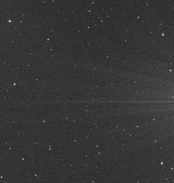
a calibrated image of 300s

stack of 70 images of 300s
TREATMENT :
Even with a significant integration of poses, a well cooled camera and good raw calibration, the noise levels in our images can often still be quite high and this is where noise reduction filters come into play during the image processing phase.
There are a multitude of noise reduction processes, with astronomical image processing software such as Pixinsight or retouching software. such as Photoshop, Lightroom, Topaz Denoise, etc ...
After experimenting with a few, the process that I have been using for some time, directly inspired by Jon Rista's tutorial, is as follows:
- linear noise reduction (before histogram rise) with Pixinsight
- noise reduction in nonlinear during histogram rise with Pixinsight
- possible last pass of noise reduction at the end of processing with Pixinsight or Photoshop.
Each of these steps will correspond to a type of noise reduction filter and the method proposed here with Pixinsight is probably transposable, at least in general terms, to other software treatment such as Siril.
The different methods presented here will allow you to choose and organize your workflow yourself. Indeed you can use:
- simple linear method in Pixinsight then simple non-linear method in Pixinsight with possibly last pass in Photoshop
- simple linear method in Pixinsight then directly in Photoshop for the non-linear part
- advanced method in linear then simple method in non-linear with Pixinsight then possibly final pass under Pixinsight or Photoshop
- advanced Pixinsight method in linear then directly in Photoshop for the non-linear part
LINEAR NOISE REDUCTION (Pixinsight):
This processing phase therefore takes place just before the histogram increases, after having first:
- selected and calibrated the brutes
- performed cosmetic correction of hot and cold pixels
- aligned, weighted, and stacked the calibrated and corrected raw
- carried out the first linear treatments (crop, reduction of gradients, deconvolution, star reduction as far as I'm concerned)
The quality and quantity of the noise reduction will depend on the establishment of appropriate masks in order to attenuate the effects of these processes in the areas of the image which must be the most spared, at the risk of destroying details or obtaining a generalized artificial effect in the image.
Two methods are offered here:
- simple, fast and efficient method
- method of Jon Rista more elaborate but more complex and long to achieve
THE ATWT METHOD :
The simple, fast and efficient method that I used before and that works very well is that of the use of the ATrousWaveletsTransform process with a Luminance mask.
The idea will be to apply a noise reduction filter while protecting very much the brightest areas of the image, little or no noise (stars, galaxy cores, structures shining nebulae etc ...) and protecting very little the darker noisy areas (sky background, bands of dust, dark nebula etc ...).
We can obviously play on the Luminance mask to protect more or less the bright areas and dark but the idea being to propose a simple technique, we will endeavor to use here a basic Luminance mask, which already offers good coherence for noise reduction.
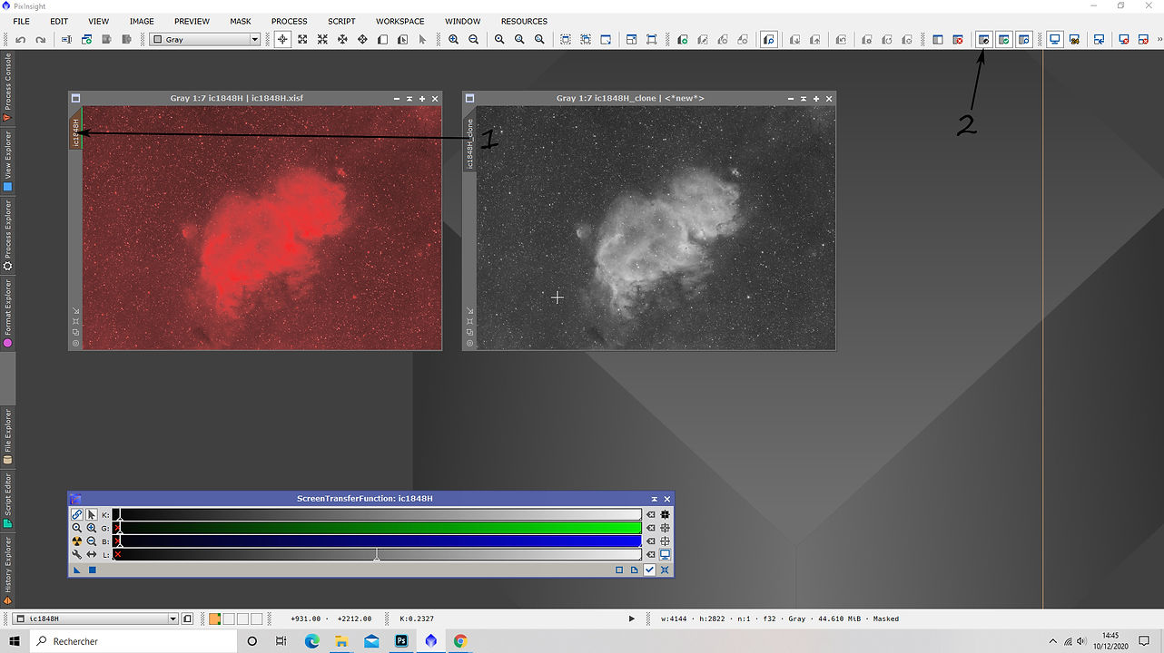
To perform a simple luminance mask in Pixinsight, you just need to:
- duplicate the linear image
- apply an STF (ScreenTransferFunction) to it
- import the values of the STF into the HistogramTransformation process (by sliding the triangle of the STF towards the bottom of the window of the HT)
- apply the HistogramTransformation process to the duplicated image (by dragging the triangle onto the duplicated image)
- remove the STF (symbol at the bottom right of the STF process)
- possibly rename this mask to Luminance_mask for example, to find your way around later because it can be used again when applying other processes later in the processing

Linear image
Duplicate linear image
A Luminance mask is therefore simply a copy of the linear image to which a histogram rise is applied with the values of the STF. This results in a non-linear image with pixel values ranging from 0 (black) to 1 (white) and which, applied as a mask, will correspond to a protection value ranging from 0 (maximum noise reduction) at 100% (no noise reduction). The protection is thus proportional to the SNR of the different areas of the image.
So we apply this luminance mask on the linear image (by dragging the image name tab of one onto the image name tab on the other) then do not forget to invert it (black button in the mask management bar, the green button used to activate / deactivate it and the blue button to display / hide it) so that the bright parts are the most protected and the dark parts the least protected from noise reduction.
On our masked image the red parts correspond to the maximum effect of the mask (maximum protection therefore no effect of noise reduction) and the black parts to the minimum effect of the mask (no protection therefore maximum noise reduction) with a gradient of the mask which is proportional to the SNR of the different areas of the image.
Now we can move on to the noise reduction step by using the k-Sigma Noise Thresholding filter of the AtrousWaveletTrasnform process without worrying about the rest of the other settings. of the window of the ATWT process which are used for other functions of this process.
The value of Threshold can be left at 3 and the number of iterations at 1, and play only on the power of the filter, namely the Amount value.

It can be useful, when finding the right Amount, corresponding to effective noise reduction while still keeping a natural aspect to the image, to use preview areas in order to check the effect of the filter on the bright parts and on the dark parts before applying it to the whole image.
For my part, I use a value of 0.5 to 0.7 for a Luminance filter image and from 0.7 to 1 for filter images RGB (which require less protection since they will be used for the color layer and not for the details or the texture of the sky background).
Preview 1 before filter
Preview 1 after filter

The idea is to obtain significant noise reduction but not noise suppression which would render the image completely artificial with a very unsightly plastic effect. It is important to seek to in particular, retain the fine grainy texture of the noise.
This is not here as the first step in reducing noise and it is therefore useless and above all unsuitable to seek to obtain a smoothed image at this stage of noise reduction (or even at the end of the total processing).
Once you get an Amount value giving a satisfactory result in the different preview areas, with details preserved while having a decrease significant noise, you can apply the process to the whole image and then move on to the next step in your processing, which in this case will be probably the histogram rise.
THE JON RISTA METHOD WITH TGVDENOISE AND MMT:
This method to the particularity of using processes with powerful adjustments while protecting the image enormously, including in the darkest areas, unlike the previous technique where the Luminance mask protected areas of the image with a proportional height of their RSB.
The two processes that will be used in this phase are:
- TGV Denoise for high frequency noise
- MultiscaleMedianTransform for medium and low frequency noise
High frequency noise reduction with TGVDenoise:
Before doing anything with TGV, it's important that we generate an appropriate mask to mitigate the effect and preserve both the fine detail as well as the fine-grained nature of high frequency noise. Preserving detail and grain is one of the key tenets of my approach, and proper masking allows both. Fine grain is essential to prevent plasticization in your images, and it generally looks better than super-smooth data. (Jon Rista)
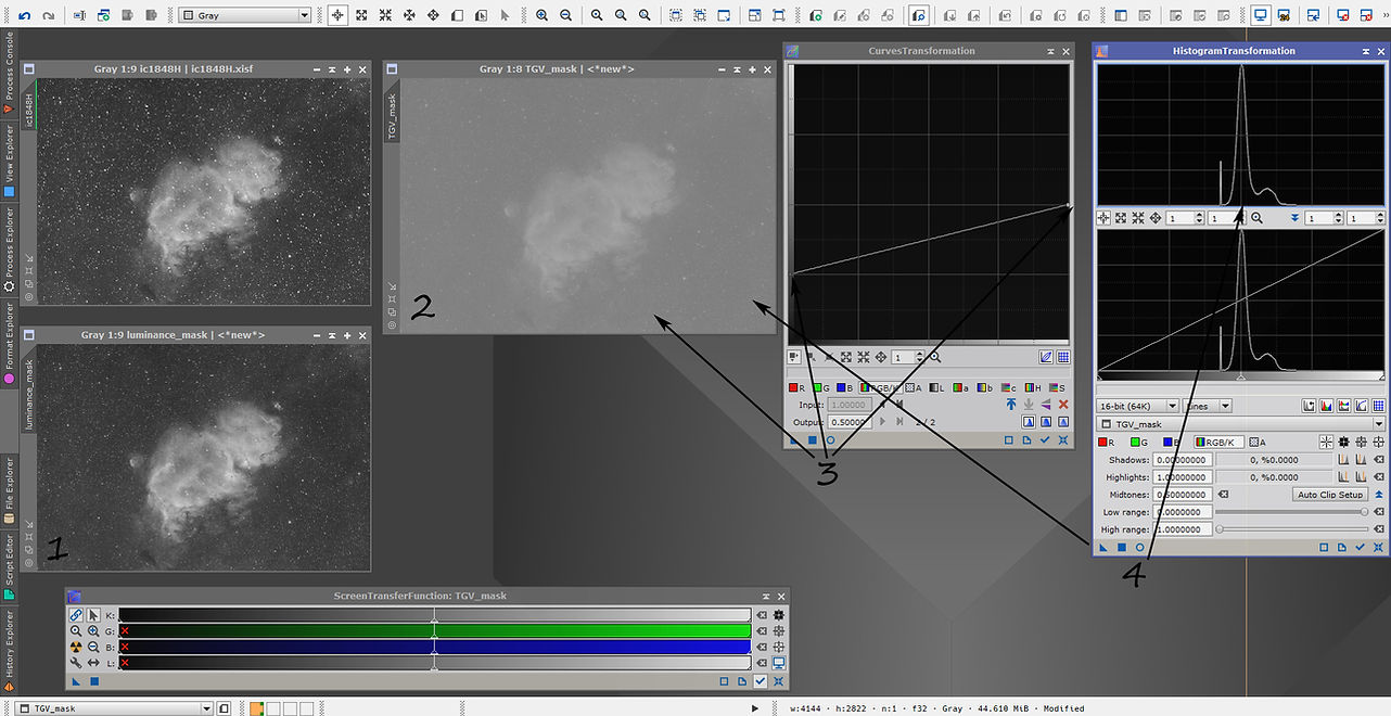
Start by creating a luminance mask with the same process as previously used (duplicate the linear image, import the values of STF on the HistogramTransformation process and apply it).
Rename this mask to Luminance_mask then duplicate it and rename the clone to TGV_mask.
The TGV mask must have a low contrast in order to offer greater protection of light areas than dark areas but by strongly protecting the dark areas all the same. This protection of the dark areas will greatly reduce the noise reduction there but will guarantee the preservation of the fine grain while allowing a significant reduction in noise.
For this we will use the CurvesTransformation process then the HistogramTransformation process :
- to reduce the contrast of the mask with CurvesTransformation adjust the level of black dot between 0.15 and 0.25 and the level of white point between 0.45 and 0.65 then apply to your TGV_mask image. the values are to be adjusted according to the initial contrast of your image (for my part 0.25 and 0.5).
- then with HistogramTransformation and move the midpoint (gray triangle slider) until the peak of the histogram is at 50%, which will brighten the mask and improve protection of the whole but especially darker areas. Here, too, you can adjust the mask's mid-tone slider depending on the protection you want to obtain. The value of 50% worked fine in my case.
We thus obtain the desired mask with low contrast and high luminosity.
We will now:
- open the TGV process and select the CIE L * a * b mode then uncheck "apply" in the Chrominance tab since we are working on a monochrome Luminance image
- apply the mask to the linear image and invert it, as in the previous method. (if you forget to invert the mask then the effect will also be inverted: the dark areas (very noisy) will be more protected and therefore less denoised than the bright areas (less noisy) which is obviously not desirable.
- select the luminance mask previously created at Support Image level from the Local Support tab, previously checked, in the TGVDenoise process.
- reduce the exponent of the Edge Protection slider to -5, which will better protect the stars and details.

We thus benefit from the internal protection of the process via the luminance mask in Local Support which will adapt the process proportionally to the SNR of the different areas of the image, coupled with the protection of our low contrast mask!
It's about now to test the settings on different preview areas of the image, as seen in the previous method, in order to find the values (Strength, Edge Protection and Smoothness) which will guarantee a good preservation of the details, a significant reduction of the noise and the preservation of the fine grain and the overall natural look of the image.
There is no here as a rule, each image, material, sky etc ... being different, but the settings base of the process, once the exponent of the Edge slider is lowered to -5, already allow a good starting point to then adjust the sliders one by one according to your image, and observe the effects brought on the previews of the light and dark areas.
If you notice that details are impaired in the bright parts, you can lower the Edge protection value.
If you are unable to achieve a natural look, especially in dark areas that are plasticizing or shedding their fine grainy structure, you can try to lower the process power strength value.
I usually leave the Smoothness value at 2.
You will notice that the process is extremely powerful despite the very strong protection applied to the image!
When looking for the right settings you can switch very quickly between the before and after views of the preview by using CTRL + SHIFT + Z and you can leave a number of process iterations at 100.
Once the good values found, start the process with a number of iterations of 500 in preview to check (the difference is very subtle but can be interesting), then run on the whole image.
If you cannot find the values that give a satisfactory result, you may have to slightly modify your TGV protective mask.


After this first phase of noise reduction in linear mode, it is possible that the TGV process leaves the image with a zoning effect, resulting in fairly extensive spots and low contrast. A subtle effect but which can prove to be unsightly and be amplified by other future treatments.
The second step of reduction in linear will allow us to correct these TGV artifacts while pursuing noise reduction.
Noise reduction at medium and low frequencies:
This type of noise is a much more difficult form to manage, and the powerful CMM process is more suitable than TGVDenoise, because of its ability to work on different scales of the image and thus to apply a different noise reduction. for each scale.
Also, appropriate masking will be necessary to preserve details and fine grain, especially as we will be working here on scales smaller than the first TGV pass, which will also further correct some artifacts that may have been left behind. by the passage of the TGV.
Jon Rista recommends a mask with even higher attenuation than that of the TGV, and we are therefore going to create a new mask by duplicating the previous luminance mask that served as a local support during the TGVDenoise and in it. applying a HistogramTransformation at 75% this time. We rename this new mask MMT_mask.
We do not use the CurvesTransformation process on this mask because we do not want it to be as low in contrast as the previous TGV mask because it is desirable to keep at this stage a protection of the shiny areas which is clearly superior to the protection of the areas. dark, although these must also be strongly protected. In other words, the protection gap between dark and light areas must be greater than at the TGV stage.
I t is therefore here a luminance mask to high brightness so that it may be necessary to extend the dynamic range with the HT process (low range / high range) if the contrast of the picture is already high base and bright areas are saturated.

Like before, we apply this mask to the linear image and do not forget to invert it then we prepare 3 or 4 previews on light, dark areas, with high presence of stars and presence of details.
Start with the following settings of the CMM process:
- Layers: 8
- Mode: Dyadic
- Target: Luminance CIE Y
Then for each layer check the Noise reduction box and give a decreasing Threshold value as the layers increase: start with 10 for layer 1, etc ... up to 2 for layer 8 as in the example following. This are the values given by Jon Rista in his article and which may need to be adjusted to obtain the appropriate result for your images of course.
The different layers correspond to the scales in the image, to the different sizes of structures.
We leave the Amount value on 1 and Adaptive on 0.

Then as before the process is applied to the various previews in order to obtain a significant reduction in high-frequency noise while maintaining a fine grain, although less present (deviation type and amplitude), and by attenuating the medium / high frequency artefacts left by TGV and which must be located at the layers 3 and 4, as well as low frequency noise.
If you do not manage to keep the grain of the high frequency noise, it may be necessary to lower the Amount of layers 1 or 2 and for the artefacts left by TGV it may be necessary to increase the Threshold of the layers. layers 3 and 4 or even 5.
It also sometimes happens that it is advisable to perform two passes to this step by lowering the thresholds accordingly, so as to born only work on the layers that require it during the 2nd pass.
I often have to spend a lot of time at this step to find the right values as we have a lot more settings. than during the TGVDenoise because of the 8 layers on which we can act with the Amount and Threshold sliders. Once the correct setting found the noise reduction is very significant and the artifacts are gone, but again remember that we are only at the first stage of linear noise reduction and there will still be a second stage when the increase in histogram then a very slight final smoothing at the end of treatment.
In addition, even after the last step, we would like some noise to remain in the image, because reduction does not mean elimination and obtaining an artificial and plasticized image. !

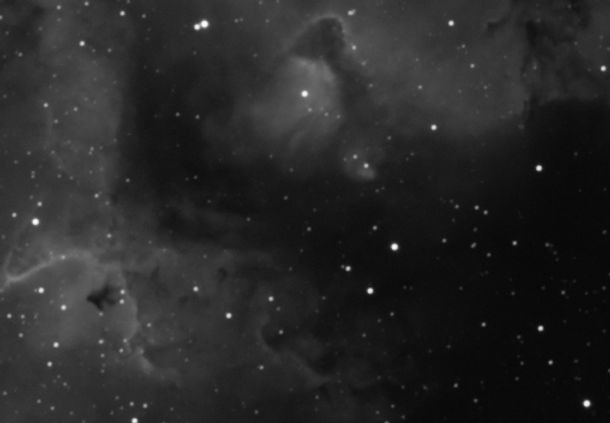
On the left a preview of the image before TGV and MMT and on the right the same area after the two processes. We see that the noise has considerably reduced while preserving the fine grain, details, and the absence of artifacts.
We can therefore move on to the second step which is that of linear noise reduction.
NON-LINEAR NOISE REDUCTION (Pixinsight)
If the previous linear noise reduction steps have been correctly performed and have given satisfactory results, then this nonlinear noise reduction step will be much faster and easier to perform.
For my part, during the histogram rise, I use the ATrousWaveltTransform process and its k-sigma noise thresholding filter, which is presented at the beginning of this article as a simple and effective method of reducing noise in linear.
Indeed this filter gives interesting results whether linear or nonlinear and it suits me personally very good for this second step, after the linear work with TGV and MMT.
The mask used will also be a luminance mask but the power of the process will be used much more lightly than during the linear phase, with this time an amount of the order of 0.1 to 0.3 (0.5 to 0.7 during the linear phase of simple noise reduction).
The peculiarity here is that this noise reduction will take place during the delinearization process, more particularly just after the first stretch, which I carry out for my part in logarithmic mode which I prefer to the masked rise of the Masked Stretch type concerning the luminance images, before continuing with iterations of the Histogram Transformation process.
You can therefore, following the previous steps carried out linearly, carry out your first stretch then duplicate the image and make a luminance mask by applying the STF values of this image with the HistogramTransformation process, still on the same principle as before.
Apply this luminance mask to your freshly stretched image and invert it then apply the k-sigma noise thresholding filter at 0.1 to 0.3 amount. The reduction at this stage must be very slight and of course respect the work done upstream at the linear stage.

You will see on the histogram that this first nonlinear pass makes it possible to reduce the foot of the curve at the level of dark tones, which will have the effect of being able to bring the black point closer to the peak of the curve when adjusting the continuation of the rise of histogram without too quickly clipping the darkest pixels.
Depending on the result obtained, it may be necessary at this stage to adjust the filter's Threshold slider, or the luminance of the luminance mask, always with a view to preserving image of excessive smoothing, loss of detail, or noise reduction artifacts.
You can then continue your histogram rise then your subsequent treatments with a good basis of noise reduction done upstream then, if you consider it necessary, it may be useful or even necessary to make a slight final pass in the case where the processing of various nonlinear accents would lead to an excessively high rise in noise.
However, it is preferable not to increase the noise too much during the following treatments by using suitable masks and by adjusting our accentuations with regard to the overall SNR of our image, so as not to having to make this last reduction too heavy.
For my part, I do this very slight last pass in post-processing in Photoshop with the noise reduction filter and a luminance mask. for an overall final smoothing but very light in the image.
NOISE REDUCTION WITH LUMINANCE MASK UNDER PHOTOSHOP:
The idea is the same as for the use of the ATWT process filter with luminance mask in Pixinsight, the aim here being to present the way of proceeding in Photoshop for those who do not work with Pixinsight or for those who like me like test different tools with different software.
This noise reduction in Photoshop that I sometimes use in the last pass can of course be applied right from the start of the nonlinear phase, but not in the linear phase since Photoshop does not allow it. Also note that the images must be passed in 16bits to work on Photoshop.
The example proposed here will therefore be done on the Luminance image at the very end of the processing, but it can be extended by adapting the parameters and is sufficient on its own as a tool for reducing the noise of an image at the different stages of the processing. if you are not using Pixinsight.
Let's start by duplicating our Luminance layer using the Ctril + J shortcut (or by dragging / dropping the layer on the + icon at the bottom of the layers window, or by right clicking on the layer and "duplicate"). We rename this new layer to "noise reduction".
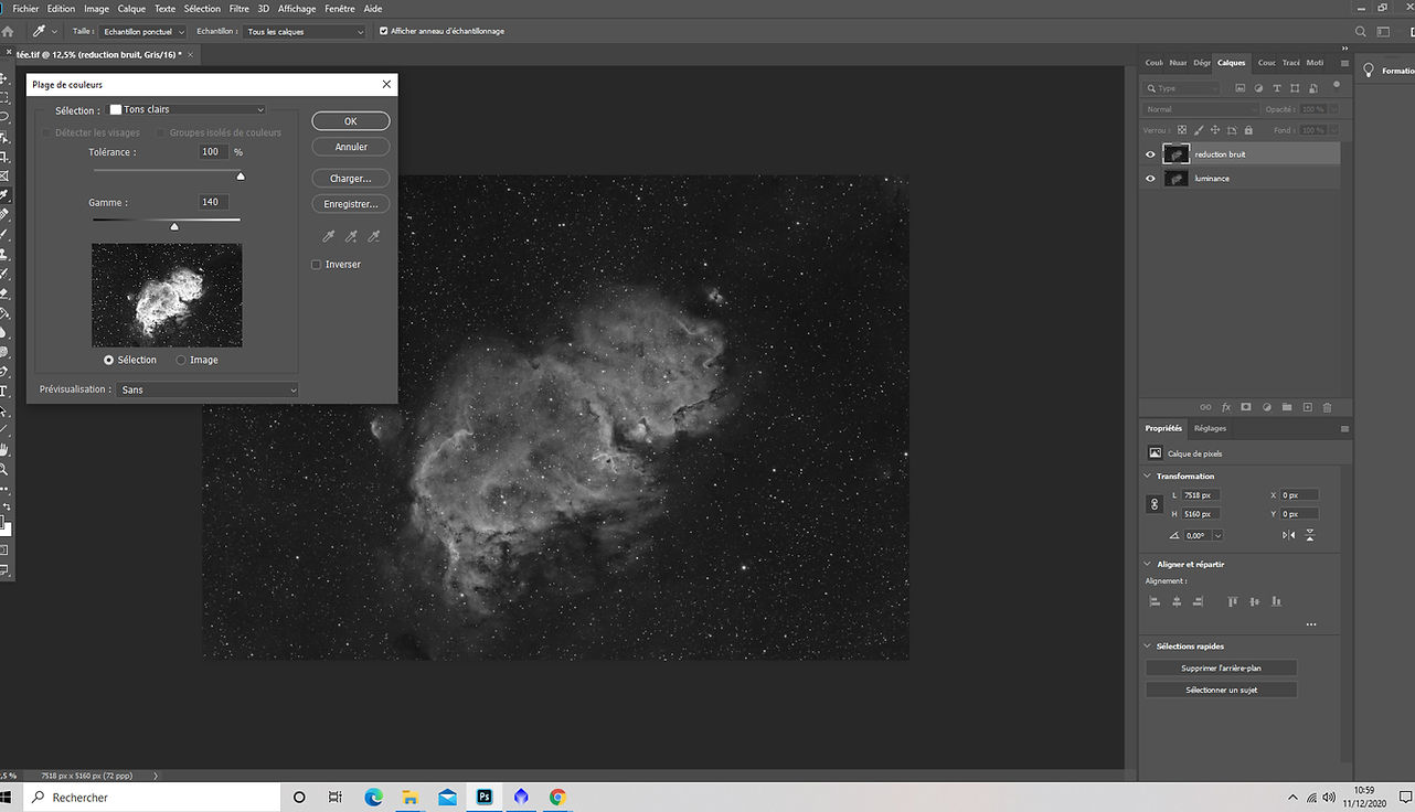
Then in order to create the luminance mask which will be used to protect the clearest, less noisy areas of the image. let's open the Color Range tool from the Selection menu.
In this tool, use "Highlights" in the Selection menu then adjust the Tolerance and Range sliders until you preview an image where the lightest parts appear white and the darkest in black, while maintaining a visibility of the shades of gray of the weak nebulosities. The white parts will be the most protected from noise reduction and the black parts the least protected, while the gray shades will receive an intermediate power. of the noise reduction filter, in proportion to their SNR (always the same principle of luminance mask).
In this example the values of 100% in Tolerance and 140 in Range give me a saturation of the brightest areas, thus guaranteeing that they will be protected at 100% during the noise reduction but it is possible that on your image it is necessary lightly apply noise reduction in these bright areas in which case you will need to adjust the sliders accordingly.
Once the setting is found, click on ok. The selection then appears in dotted lines on your layer, then let's create a layer mask on the reduction layer noise by clicking on the layer mask icon at the bottom of the layers window. The selection made with the color range tool then automatically appears in the created mask.
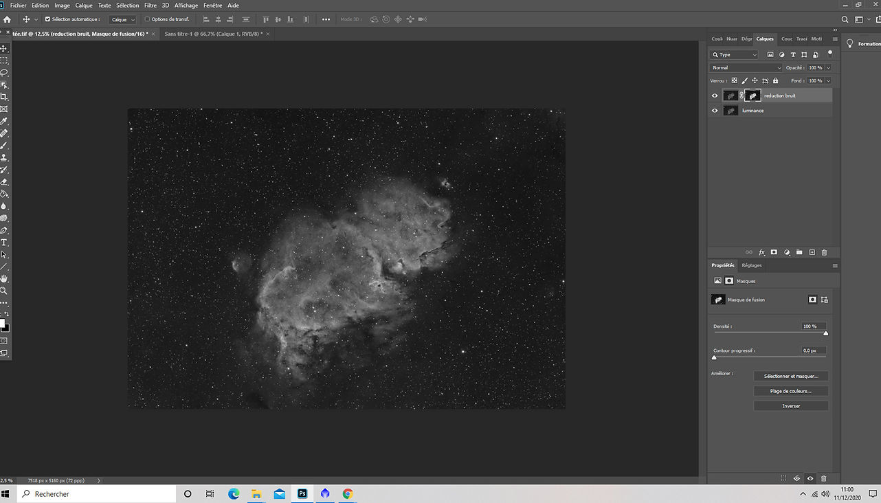
Then we will invert this mask by going to the mask (alt + left click on the mask) and using the shortcut Ctrl + I (invert).
The areas protected by the mask will then appear in black, the areas where the effect will be maximum will appear in white, and all shades of shades of gray will receive the effect of the mask proportionally. to their signal-to-noise ratio, which is precisely the desired effect.
Note that from the previous step we could have created this inverted layer mask by holding the Alt key and clicking on the layer mask icon.

So here is our reduction layer noise correctly protected by this luminance mask and we can now apply the filter using the noise reduction tool in the Filter / Noise / Noise reduction menu.
Depending on the desired power you will have two sliders to adjust: Intensity and Keep details.
For my part, I generally leave the conservation of details at 100% and play with the intensity of the filter, but it is possible that an intensity of 10 is not yet sufficient in certain cases, in which case you can lower the conservation slider. details (which is not a problem since your mask guarantees the protection of details and stars and this filter will apply especially to the darkest areas of the image).
In my case of the last final noise reduction pass after performing the previous steps in Pixinsight, the setting will therefore be very light in Photoshop. But in the event that you perform your noise reduction entirely in Photoshop, the sliders and possibly the mask will have to be adjusted accordingly.

Once the correct setting found by monitoring the different areas of the image with the preview to ensure that details are spared, and that the reduction filter does not introduce not artifacts, nor does it remove the fine grain of the noise, you can apply by clicking OK.
If need to adjust the protective mask it is quite simple use the Brightness / Contrast tool from the Image / Adjustments menu by positioning yourself beforehand on the mask (Alt + click on the mask). You will be able to:
- increase or decrease its brightness in order to either enhance either to reduce the protection of the darkest areas or the lightest areas
- increase or decrease its contrast in order to increase or reduce the difference protection between dark and light areas